Pickups part 4 - Calculating the inductance of rectangular coils
- G7D30N
- Dec 13, 2022
- 3 min read
Updated: Dec 17, 2022
As always thanks to the members of the Audio Electronics DIY Discord server for their continued support and motivation.
Unfortunately a large amount of the calculations below may be deeply flawed. I am leaving this article up in its current state as I feel the method and underlying thought process are valuable. However I do not believe the final figure is accurate. Once I have a physical model to measure I will update this article and subsequent articles with the measured value.
Many resources exist online for the calculation of planar spiraling inductors. Unfortunately, very few of them address the case of the rectangle. This paper by Sunderarajan S. Mohan Et al. proposes a number of different methods for calculating the properties of a square spiraling inductor, as well as a number of other interesting shapes. From here we can develop an empirical model that applies to rectangular coils. But first some theory
Inductors in series
Considering only a single layer of PCB, any inductor we make will consist of a set of concentric rings of wire all in series. When inductors are in series, the total inductance is calculated by the sum of the individual inductances and the sum of their mutual inductances m. m is derived from the properties of the coils themselves, and is a function of their relative positions, orientations and a number of other factors. The sum of k inductors in series can be expressed via the following formula, where M is the sum off all mutual inductaces m

Building a model to calculate M
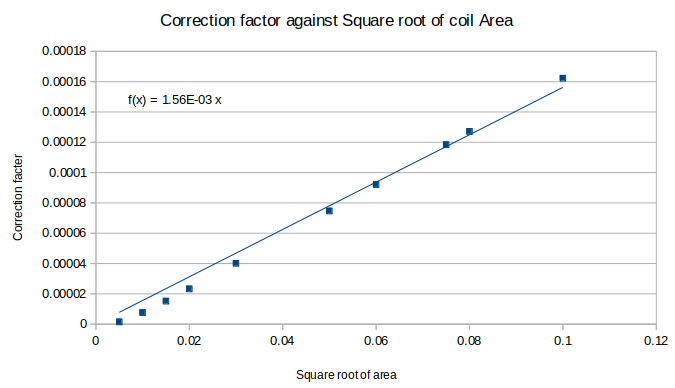
As we are assuming M to be a constant, we can calculate this empirically. By calculating the total inductance, L, and subtracting the sum of the individual inductances we are left with M. Given that we know the formula for a square inductor, and that by using the method outlined in the 1999 paper we can calculate the total inductance of a square spiral, we can easily calculate the value of M for different spiral types. I have exclusively used spirals with 20 turns with a spacing of 0.09mm and a thickness of 0.09mm, as that is what my PCB will eventually use, but this method will work for any planar inductor. Creating a bunch of hypothetical test coils and plotting the correction factor M against the square root of the coil area (obviously this is just the side length in this case but because we're dealing with 2D shapes and areas I have chosen to represent it this way) leads to the following graph.

Holy crap that's a nice linear relationship! If we now assume that rectangles are just squares that are #notlikeothersquares, then we can assume that the same relationship holds true for rectangular inductors. The constants are likely to be slightly different, however the orders of magnitude will be similar. Now we simply need to calculate the sum of all the individual rectangular coil inductances and we can have an estimate of the per layer inductance of our design.
...Simply...
The rectangular case
The formula for calculating the inductance of a rectangular coil with outer dimensions W and H, and a wire diameter of D is the following

This mess will allow us to calculate the inductance of each individual turn of our rectangular coil. Using the relationship we derived earlier, and assuming our rectangles are actually squares with a weight problem, we can simply sum the individual coils, then add a value of M based on the above graph. In this case each individual layer has an inductance of 4.9E-5H, or 49μH. However, unlike the cases of resistance and capacitance, we can't simply stack them on top of each other and call it a day. Much like a set of concentric inductors, a set of stacked inductors will have a large amount of mutual inductance that needs to be determined empirically.
Stacks of Spirals
Much like the case above, we are going to create a stack of 100 single turns of copper with varying area and calculate their individual inductances. To do this we use the formula above. In order to minimise variables, the ratio of sides was kept constant. We then calculate the inductance of the stack using the following formula

Where L is again the total inductance, μ is the vacuum permeability, N is the number of turns, A is the coil area and l is the length of the coil. We can then use this to calculate a correction factor as above. When plotted against the inductance of a single layer, the following graph was obtained.

Using this relationship, an inductance of around 10H was calculated per pickup. This is likely to be larger than the true value since square inductors have a higher ratio of side length to area than rectangular ones, and will therefore likely have a slightly higher correction factor than rectangular inductors, which will influence the overall per layer inductance.

Comments